This project was seen in an old edition of Model Engineer's Workshop, #149 and implemented during a cold December ten years ago. Moving my local electronic notebook to the web on GitHub has spurred me to write up some of the older projects, that were just recorded in a paper notebook.
A sensitive drilling jig is used for drilling very small holes in metal. It is very easy to break off a small drill when drilling. This is most often because the chips are not easily cleared from the hole. The drill binds and snap: the part is ruined. This jig is designed so the drill is held by hand and can easily be removed from the hole to clear chips. It consists of three parts, one of which can be screwed to a small drill chuck for holding the drill. The sleeve was the first part made and is diagrammed below.
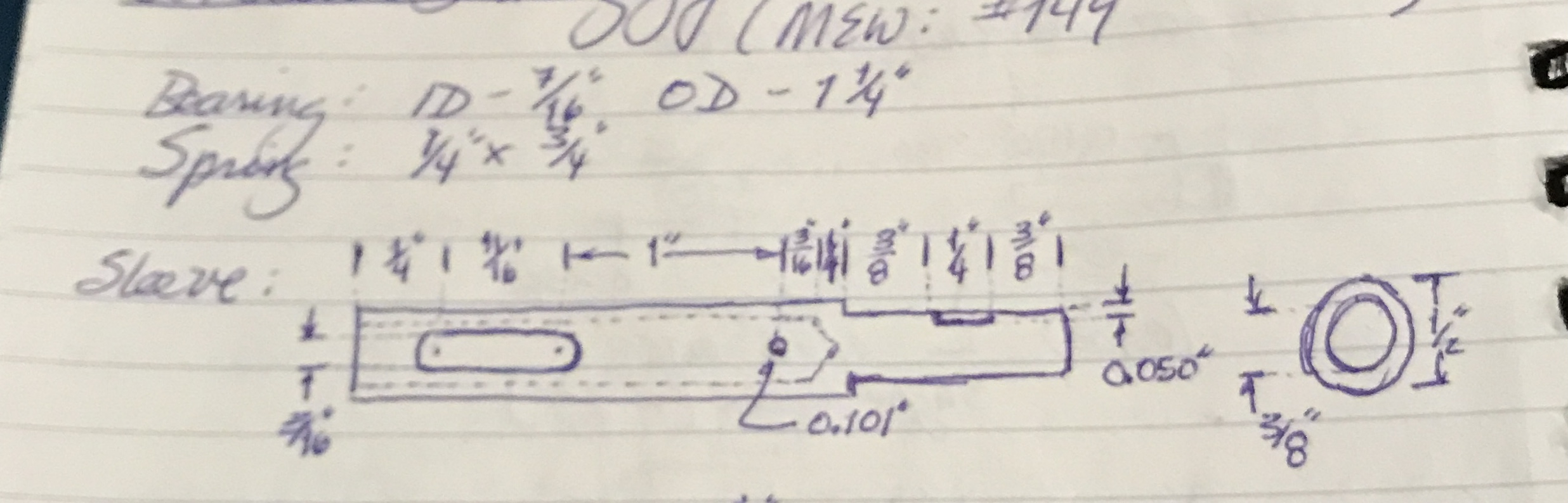
The notebook photo above also points out the two purchased parts for this jig: a bearing, 7/16" ID & 1 1/4" OD and spring, 1/4" X 3/4". The sleeve was made from 1/2" steel hex. A 3 1/8" length was cut off with a hacksaw. One end was faced and the diameter of the faced end was reduced to 0.375" for 1". (This is the diameter needed to fit the end mill adapter on the Sherline Mill.) This part was then clamped in the vise on parallels. A slot was milled 0.050" deep with a 0.250" end mill 3/8" from the end. This slot serves as a spot for the adapter's set screw to hold.
The reduced end was placed in the end mill adapter and this was screwed to the spindle of the lathe ensuring that all subsequent operations would be concentric with the reduced portion. The distal end was faced, center drilled, and drilled up to 23/64" for a depth of 2 1/8". The hole was reamed to 3/8".
The part was returned to the end mill to drill holes and make the slot. The sleeve was clamped to an angle plate with a machinist's jack supporting the round end. A strap clamp was situated over the machinist's jack and sleeve holding it tight. The part was squared up to the table with a dial indicator to < 0.001". The end was located as was the center of the hex stock (0.285"). The table was moved 1 15/16" from the non reduced end. It was center drilled and drilled through with a #38 drill (0.101"). This hole is for a pin driven in later.
The table was moved back 1". The sleeve was drilled through one side with first a center drill and then a 3/16" drill. After moving back another 11/16" the drilling operation was repeated. A 3/16" end mill replaced the drill chuck in the spindle and the two holes were connected by milling out the steel between in 0.01" increments to complete the slot. The sleeve was cleaned up with a file to remove burrs and then it was sanded with 150 grit paper.
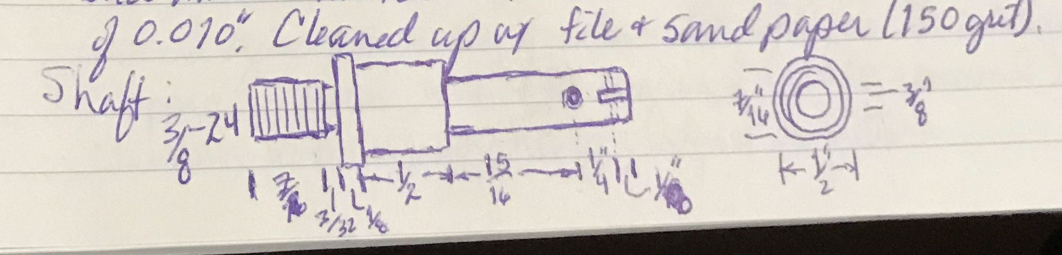
The plan for the shaft that slips in and out of the sleeve is shown below. The shaft was made from a 2 1/2" length of 1/2" steel round. This steel was held in a 3-jaw chuck and the diameter was reduced to 0.429" (slightly less than 7/16") for 1 11/16" giving a sliding fit in the bearing. 1 3/16" of this reduced end was further reduced to 3/8" diameter for a sliding fit in the sleeve. This part was moved to a 4-jaw chuck and carefully centered on the 1/2" segment to maintain concentricity. The opposite end was reduced to 3/8" for 11/16" for threading. A groove was cut with the cutoff tool to a depth of 0.03" and 0.07" wide. The end was chamfered and 3/8"-24 threads were cut by single point threading to a depth of 0.03". This was a nice fit with the small drill chuck.
The shaft was clamped on the Sherline mill table with small vee blocks and 1-2-3 blocks. It was drilled and tapped 6-32. A matching screw was cut to length. The screw head was reduced in the lathe to fit in the sleeve's slot. The shaft was rotated 90° to drill the 0.101" hole (1/8" from the shaft end) through to fit the second spring holding pin. Finally, a slot (allows the spring to be held by the pin) was cut in the end of the shaft with a 0.057" slitting saw. The slot was cut to a depth of 3/16".
The two pins needed were cut from 1/8" brass rod. The 1/8" stock was reduced to fit the drilled holes and two lengths were cut off: 3/8" and 1/2". The 3/8" pin was shortened a bit as its corners stuck out impeding sliding in the sleeve. The hand wheel for the jig was cut from a 2" aluminum round 1/2" thick. The piece was faced on both sides. It was drilled up to 27/64". The hole was opened by boring to 1.25" to fit the bearing. The hand wheel was held in the vice in the mill and drilled through the side and tapped for a 10-32 set screw. An auxiliary plate was made to hold this wheel to the rotary table. The wheel was aligned with the spindle and then shifted off center by 1.10". A 1/4" end mill was used to mill slots down the side of the wheel. The rotary table was turned 30° and the milling was repeated for a total of twelve slots.
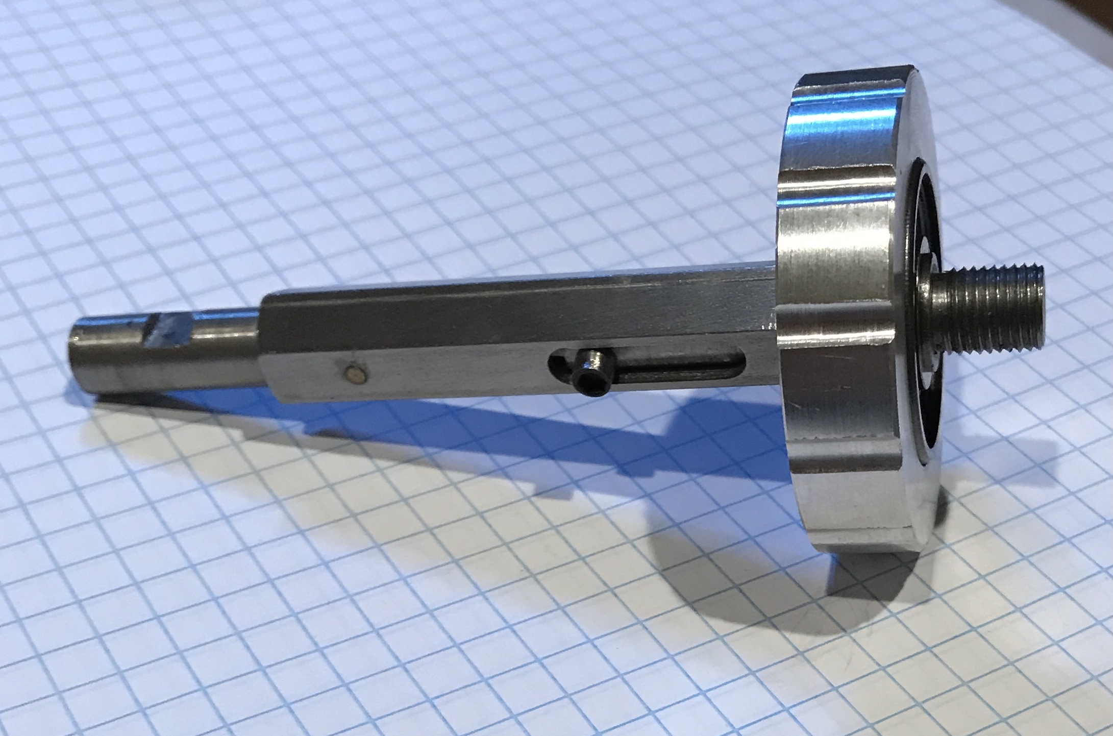
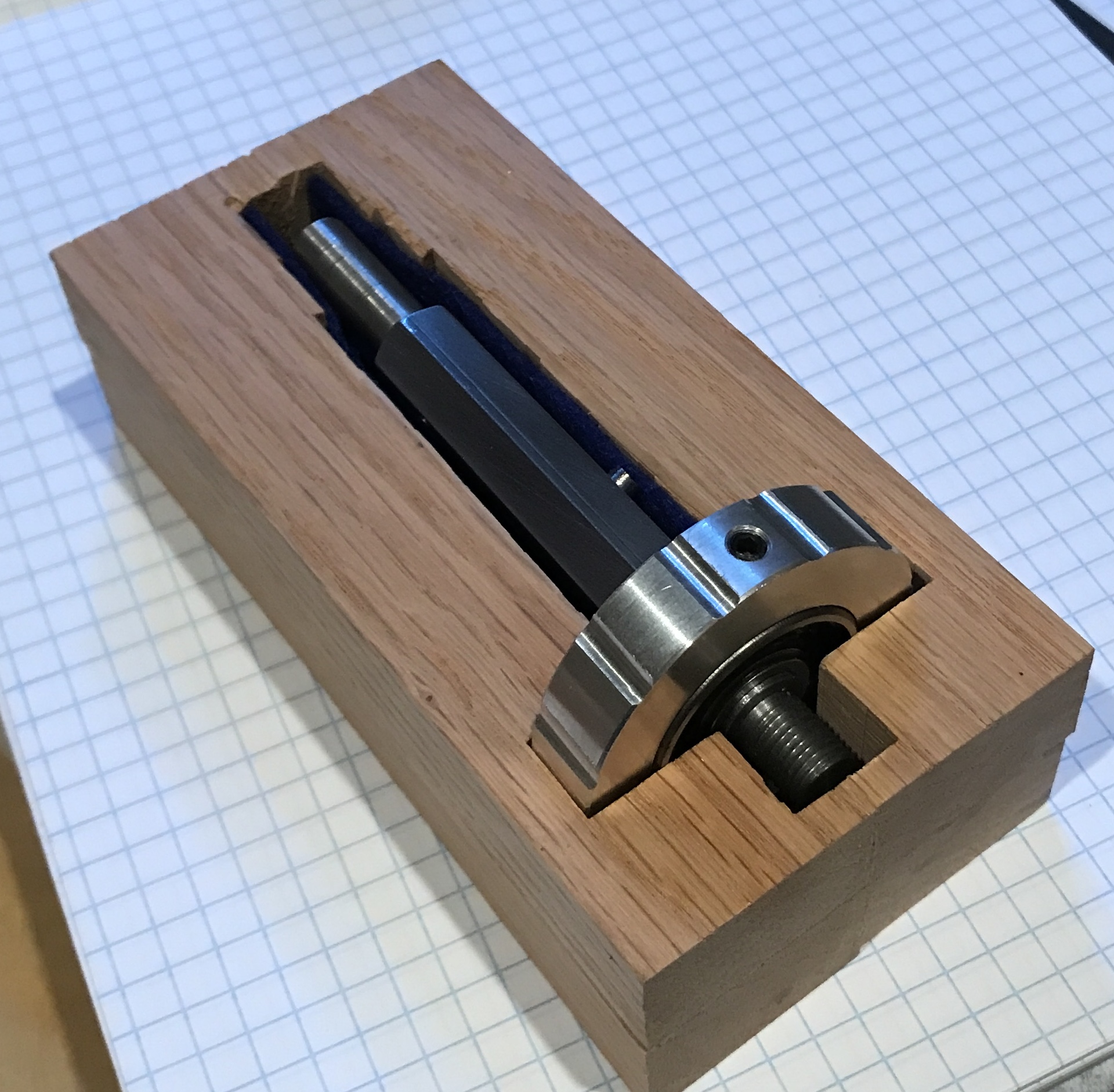
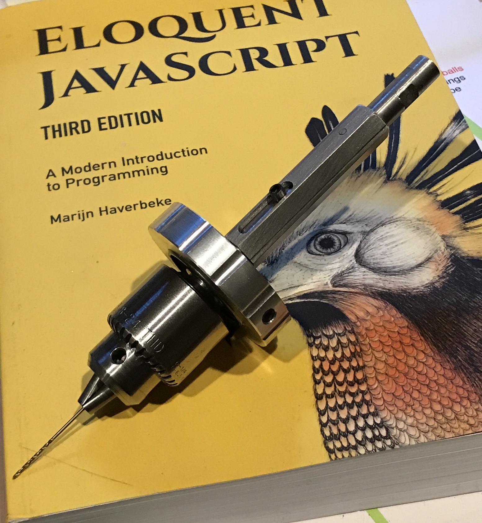
This completed all of the parts for the sensitive milling jig. It was assembled with the spring held between the pin through the sleeve and the pin through the shaft. The bearing was held with the set screw in the hole of the hand wheel. The first picture below shows the completed and assembled jig. The second shows the holder made for it with felt lining. The third photo shows the jig attached to a small drill chuck sporting a tiny 0.040" drill (#60).